

How to Use Thermal Imaging Camera Like a Pro
You point a thermal camera at an electrical panel and see a bright yellow patch around one breaker. The instinct is to call it an overload, but the image might be showing reflected heat, a poor angle, an incorrectly configured emissivity value, or a target that's too small for the camera's measurement geometry.
The practical answer to how to use a thermal imaging camera is to treat it as a measurement system, not a colorful visual thermometer. Control the environment, configure emissivity and reflected apparent temperature, keep distance and angle consistent, save radiometric images, and interpret patterns against comparable components and operating conditions. Updated for March 2026.
Why Your Thermal Camera Lies to You
A shiny electrical panel cover can show a dramatic hotspot that has little to do with the circuit behind it. Metal may reflect your body, a nearby motor, or sunlight, and the camera can display that infrared energy as if it came from the panel. Move sideways. If the hotspot moves with you, you are seeing a reflection, not proof of a failing breaker.
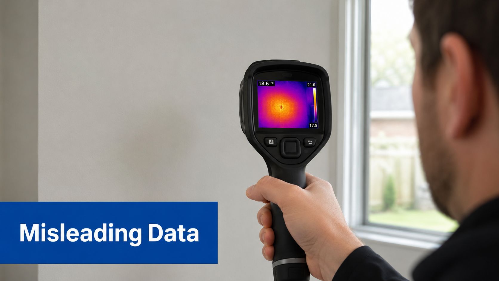
Thermal cameras detect infrared radiation and convert it into a temperature estimate. The result depends on the material, surface finish, viewing angle, reflected surroundings, humidity, distance, and camera settings. A matte painted wall is usually easier to measure than polished copper, stainless steel, glass, or glossy plastic.
A reliable inspection starts before you press the trigger. Examine the surface for gloss, moisture, dust, obstructions, or other conditions that can alter the infrared signal. For building work, wait until at least 2 hours after the sun has left the surface, as advised in the thermal imaging camera user guide for building inspections. Insulation and energy-loss checks also work better when indoor and outdoor temperatures differ by at least 10 °C, according to that guidance.
Keep direct sunlight off the lens, and be cautious with wet surfaces, unstable conditions, high humidity, and blocked sight lines. Change your position whenever a hotspot looks unusual. A genuine defect remains tied to the physical target, while a reflection often shifts as your viewing angle changes. Distance matters too. If the target is smaller than the camera's measurement area, the displayed temperature may blend the target with its surroundings.
Practical rule: A thermal image is evidence for a diagnosis, not the diagnosis itself.
Used properly, the camera can expose temperature patterns around electrical connections, ductwork, insulation, bearings, circuit boards, and heat exchangers that are not obvious visually. Phone-connected and standalone models both require the same discipline: verify the environment, understand what the detector measures, and compare similar components under similar operating conditions. The explanation of what a thermal imaging camera measures provides useful background before you interpret palettes or temperature markers.
Setting Up Your Thermal Camera for Accurate Readings
Phone-connected cameras are convenient, but they add failure points that standalone imagers largely avoid. The camera must have power, the phone must recognize the accessory, the app must have the required permissions, and the connector must fit securely. A loose connection can look like a dead camera, while a dirty lens can look like a focus problem.
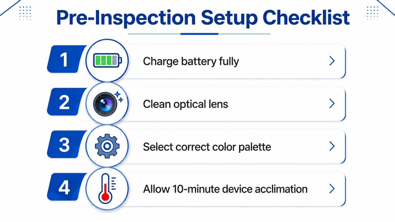
Start with a repeatable preparation routine:
- Charge the camera and phone. A low battery can cause shutdowns, connection instability, or inconsistent operation during a long inspection.
- Install the companion app. Check for current app and firmware versions before leaving for the job.
- Fit the connector carefully. Phone-mounted units may need physical adjustment to match a case, port position, or connector style.
- Approve accessory permissions. Android and iOS may ask for permission to use an external accessory, Bluetooth, Wi-Fi, or location services. Denying one can prevent pairing or image transfer.
- Clean the lens correctly. Use a suitable lens-cleaning material and avoid touching the optical surface with bare fingers.
- Select the palette for the task. A simple grayscale or iron-style palette may make broad gradients easier to read, while a high-contrast palette can help isolate a small anomaly. The palette changes interpretation, not the underlying heat.
- Confirm radiometric capture. Make sure the camera saves radiometric images rather than only ordinary JPEG files. A radiometric file preserves measurement information for later analysis.
- Allow thermal stabilization. Let the system reach a stable operating condition before relying on temperature readings.
For human-temperature screening, the BIPM guidance specifies a controlled environment of 18 °C to 24 °C, relative humidity of 10% to 75%, no draft, no dust, and no reflective backgrounds. It also recommends turning the system on at least 30 minutes before measurements. Those controls are described in the BIPM-focused thermal measurement guidance.
Standalone and phone-connected workflows
A standalone camera usually gives you a screen, controls, storage, and a stable physical package. Phone-connected models often provide a larger display and easier sharing, but app permissions, firmware, connector fit, and phone cases complicate the workflow. Before blaming the sensor, test the connection with the phone case removed, clean the lens, restart the app, and re-pair the accessory.
The camera's field of view and target framing matter just as much as resolution. A target that occupies only a small part of the image may not contain enough pixels for a dependable spot measurement, even if the image looks sharp to your eyes.
Record the operating load, distance, angle, ambient conditions, camera model, emissivity setting, and reflected apparent temperature with every important capture. A tripod helps reduce shake and makes repeat inspections easier, especially when you're comparing the same asset over time.
Mastering Emissivity and Reflections in the Field
A thermal camera can show a clean hotspot while measuring the room, the sky, or nearby equipment. Emissivity describes how effectively a surface emits infrared radiation compared with an ideal emitter. In fieldwork, that setting controls how much of the signal the camera assigns to the target instead of reflected energy.
Bare, polished copper is difficult to measure because it reflects its surroundings. Where equipment safety and site procedures allow, apply electrical tape or another safe, matte, high-emissivity proxy to a suitable area. Let the proxy reach the same thermal condition as the component, then configure the camera for that surface before taking a reading.
Do not treat every electrical component as a surface with emissivity near 0.95. The FLIR guidance on quantitative thermal imaging identifies an assumed emissivity, ignored reflected background temperature, changing angle, and changing distance as common causes of unreliable trend comparisons.
Common surface emissivity values
| Surface material | Approximate emissivity | Measurement notes |
|---|---|---|
| Matte black tape | High | Useful as a proxy target when applied safely and allowed to reach thermal equilibrium |
| Painted or matte surfaces | High | Usually easier to measure than polished metal |
| Bare copper | Low and highly reflective | Reflected apparent temperature can dominate the reading |
| Shiny metal | Low and angle-sensitive | Change position to test whether the hotspot moves |
| Glass or reflective windows | Variable | Often shows reflected surroundings rather than the object behind it |
Use this table for field comparison, not as a replacement for manufacturer data or a validated camera setting. Paint condition, oxidation, dirt, surface finish, and viewing angle can all change the result.
Reflected heat and viewing angle
Set both emissivity and reflected apparent temperature before recording quantitative readings. Reflected apparent temperature represents infrared energy from the surrounding environment that bounces off the target and reaches the camera. On a reflective surface, ignoring it can produce a precise-looking marker with a misleading physical meaning.
Change your position instead of changing the color palette. If the apparent hotspot shifts as the camera moves, reflection is a likely cause. Avoid perpendicular views of shiny targets. If the application permits, use a safe, high-emissivity proxy and measure that area consistently.
ISO 10880 guidance recommends an observation angle of 45° or less, with up to 60° acceptable. It also requires the lens and distance to suit the camera's spatial resolution and instantaneous field of view. Within the manufacturer's specified environment, the cited radiometric benchmark is ±3 °C or ±3% of the reading. These angle and measurement points are summarized in the ISO 10880 thermal measurement guidance.
Distance creates a separate error. As the camera moves away, the measurement spot covers more physical area. The distance and spot-size inspection guide notes that temperature error rises rapidly and non-linearly when a hotspot fills less than about 70% to 80% of the spot area. A small connector can then be averaged with the cooler panel around it.
Keep the target large within the measurement area for quantitative work. Beyond 20 meters, treat readings as generally qualitative unless they have been validated. Phone-connected cameras need the same discipline as standalone units. A larger phone display does not correct poor emissivity, reflections, or an oversized spot. Capture the distance, angle, surface setting, and environmental conditions with important images so another technician can judge the reading rather than trust the color alone.
Real-World Inspection Scenarios and What to Look For
A thermal camera earns its place in the field when it reveals a repeatable difference under known operating conditions. Compare similar phases, terminals, duct sections, or components before treating one bright area as a fault.
Electrical panels
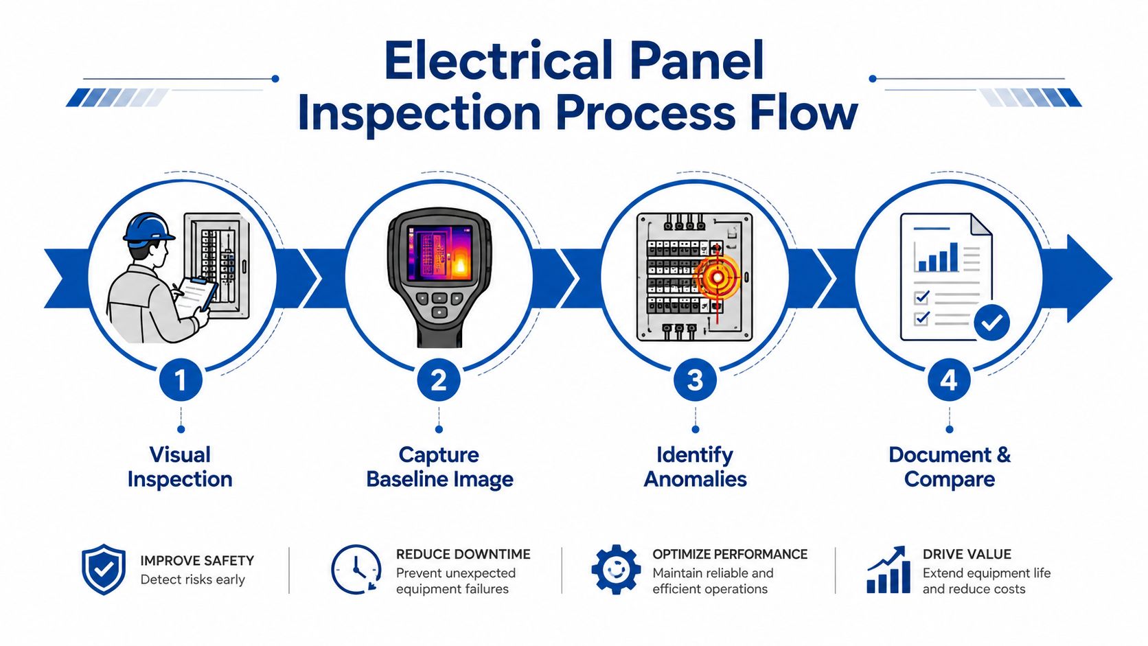
Begin with a visual inspection, then scan energized equipment from a safe position while the system carries a representative operating load. Detailed imaging of live conductors should be performed at more than 500 mm from the conductors. That distance does not replace PPE, arc-flash boundaries, access controls, or site procedures. Follow the requirements in this electrical thermal inspection safety guide.
Look for an outlier within a comparable group. Compare phases, parallel conductors, breakers serving similar loads, and matching connection points over time. A loose termination can appear warmer than its counterparts. An overloaded circuit may produce a wider heat pattern across the conductor and protective device. Check the pattern against load information, then have a qualified person assess the equipment before it is opened or serviced.
Record more than the image. Save the operating load, ambient conditions, camera position, and measurement settings. A narrow spot reading has little value if the target does not fill enough of the spot, so focus carefully and keep the measurement geometry consistent.
HVAC and building envelope
Insulation gaps, duct leakage, blocked vents, and uneven heating depend on thermal contrast. A dramatic color palette does not prove a defect. For insulation and energy-loss checks, allow the surface to settle after solar exposure and work with a meaningful indoor-to-outdoor temperature difference, as outlined in this building inspection guide.
A missing section of insulation may form a continuous warm or cool band. Duct leakage can create a localized pattern that follows airflow or changes around joints. Wet surfaces, direct sunlight, and unstable weather can imitate both signatures. Inspect the surface, check the building conditions, and repeat the scan when the contrast is more stable.
For leak-focused work, use this thermal camera guide for water leak investigation to structure the search. Confirm the thermal indication with moisture measurements or other building diagnostics. A thermal camera locates a suspicious pattern, it does not identify the source by itself.
Phone and PC mainboards
Board-level inspection needs close focus, stable positioning, and a target large enough for the camera's optical resolution. One inspection camera specification lists a minimum focal distance of 4 cm and a spot size of 52 µm per pixel at minimum focus, showing why small components quickly exceed the limits of a general-purpose phone-connected camera. Review the cited inspection camera specification when choosing equipment for this work.
Use a narrow field of view, focus on the component, and compare the board before and after power is applied under the same controlled test condition. A shorted component may produce a concentrated heat signature. A processor or power-management area may warm normally during operation, so diagnose the pattern against board layout, current draw, voltage measurements, and operating state.
A cool component can also indicate a missing heat path. Color alone cannot distinguish a fault from normal behavior.
Common Mistakes That Invalidate Your Thermal Data
A thermal image becomes unreliable when the operator records the color pattern but not the conditions behind it. Without emissivity, distance, viewing angle, equipment load, and ambient context, a colorful JPEG may be impossible to compare with a later inspection. Save those details with every inspection record.
Treating every surface as high emissivity creates false confidence. Bare metal, polished terminals, and glossy covers can reflect nearby heat sources instead of showing their own surface temperature. Set emissivity correctly, account for reflected apparent temperature, and use a safe high-emissivity proxy where appropriate.
Keep the measurement geometry consistent. A close, straight-on image compared with a distant image taken from another angle can show a temperature difference caused by setup rather than equipment deterioration. Keep the camera position, lens, angle, palette, focus method, and measurement settings consistent.
Before-and-after check: If a hotspot moves when you move, investigate reflection first. If it stays tied to the same physical connection and differs from comparable components, investigate the equipment.
The phone-camera failure modes
Phone-connected cameras introduce their own failure points:
- Permission failure: The phone may block the accessory, app, Wi-Fi, or location permission required for pairing.
- Connector mismatch: A phone case or loose connector can interrupt the data path.
- Firmware mismatch: An outdated camera or app can cause unstable operation.
- JPEG-only capture: Without radiometric data, later temperature analysis is limited.
- Dirty optical surface: Smears and dust reduce clarity and can resemble a focus problem.
The FLIR phone-connected camera quick-start guidance follows the practical setup order: charge the camera, install the app, adjust the connector, and pair the phone before capturing an image.
Long-range quantitative readings create another common error. The measurement spot grows with distance, so a small target can be averaged with its surroundings. Move closer when safe and practical. If that is not possible, report the image as qualitative unless the camera and inspection method have been validated for that distance.
For electrical work, maintain a consistent asset record and follow related practices described in this 20 amp outlet wiring guide. Thermal imaging identifies a pattern. Electrical testing and code-compliant repair still determine the fault and the corrective work.
Safety Protocols and Troubleshooting Connection Issues
During a live electrical inspection, keep more than 500 mm from energized conductors when detailed imaging is required. Follow the site's PPE and arc-flash procedures, stay within your training, and never remove a barrier or protective item to improve the view. The electrical thermal inspection safety guidance provides a useful reference for this discipline.
Use a controlled troubleshooting sequence rather than changing several variables at once:
- Blurry image: Clean the lens, set focus correctly, and move close enough for the target to fill the measurement area.
- Connection drops: Remove the phone case, reseat the connector, confirm permissions, then repeat Wi-Fi or accessory pairing.
- Inconsistent temperatures: Check battery level, allow the camera to stabilize, and review emissivity, reflected apparent temperature, viewing angle, distance, and ambient conditions.
- Missing analysis data: Confirm that radiometric capture is enabled instead of saving an ordinary image only.
- Persistent faults: Stop using the readings for decisions and contact the manufacturer or a qualified service provider for calibration or repair.
Validate a phone-connected camera against the accuracy specification for the intended surface and environment. A target that is reflective, small, or poorly framed can produce larger errors, particularly when it does not fit the camera's measurement resolution. The thermal measurement workflow guidance explains how measurement setup affects the result.
For phone and accessory faults, use this phone-to-projector connection guide as a practical reminder to isolate physical connection, permissions, pairing, and software variables separately.
Use thermal imaging to narrow the diagnosis, document evidence, and identify where electrical or HVAC testing should follow. That workflow makes a pocket camera or standalone imager useful in real field conditions.
DigiDevice offers thermal imaging cameras compatible with Android and iOS, along with electronics tools for phone and PC diagnostics. Visit DigiDevice to compare models and check the current price before choosing a camera for your inspection workflow.