

How to Install Rooftop Antenna
You've climbed back down from the roof, the ladder still wobbling under your boots, and the local news is frozen into pixel blocks. The tempting answer is to drill in a taller mast, but a successful rooftop antenna job starts earlier. Test reception, confirm the installation is allowed, and plan the grounding path before you buy hardware or step onto the roof.
Updated for March 2026, this guide covers how to install rooftop antenna equipment with the practical trade-offs that matter, from roof access and mount selection to coax routing, lightning protection, aiming, and final verification.
Decide Whether a Rooftop Mount Is Worth the Climb
A rooftop location can help when the antenna needs a clearer path toward broadcast transmitters, but height alone doesn't guarantee usable reception. Nearby metal roofing, foil-faced insulation, roof structures, and other obstructions can interfere with the result, so treat the roof as one candidate location rather than an automatic upgrade.
Run three checks before buying a mount
First, check the proposed location. Use your full address with the FCC DTV reception tools or another reputable tower-location service to identify transmitter direction. Then compare that direction with the roof, attic, window, and wall locations available to you. If an attic or exterior wall produces the channels you need, it may deliver the practical result without exposing you to roof work.
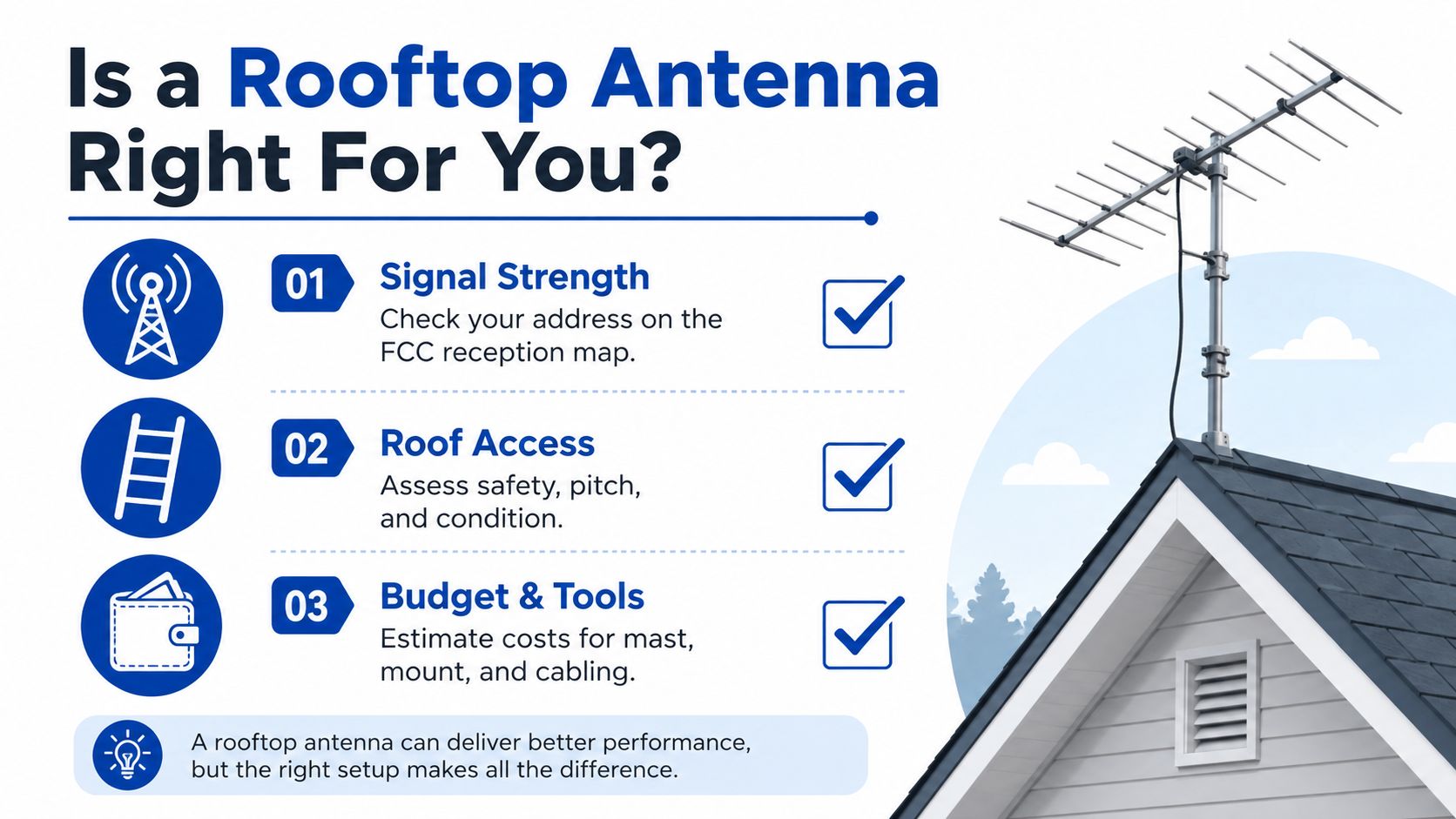
Second, check permission and code eligibility. FCC OTARD protections cover certain antennas installed in areas under a property owner's or tenant's exclusive use or control. They don't generally cover common areas, including shared roofs and exterior walls in multi-dwelling buildings, and they don't cover antennas used for AM/FM radio, amateur radio, CB radio, or digital audio radio services. Covered equipment includes local television broadcast antennas and certain dishes or broadband antennas no larger than one meter, as described in the FCC's consumer antenna guidance.
OTARD protection also doesn't erase local safety requirements. Check municipal permit rules, HOA documents, roof warranties, and restrictions on exterior hardware or roof penetrations. A city may require permission for a tall mast even when the antenna itself is protected.
Third, test signal potential before permanent mounting. Place a portable antenna at the intended attic, window, balcony, or roof-edge position, then scan for the specific channels you care about. Rotate it toward the strongest transmitter cluster and test again. This simple trial often reveals that the higher-risk location adds little, while a safer position works well.
For broader home connectivity planning, compare the rooftop decision with this guide to boosting cell signal at home. A TV antenna and a cellular booster solve different reception problems, so don't use one as a substitute for the other.
Put safety gear first
Before tools, prepare a rated roof anchor and compatible harness, non-slip boots, work gloves, safety glasses, and a ground spotter with a charged phone. Don't work near overhead power lines, wet roofing, strong wind, or a roof surface you can't safely traverse.
Keep the equipment practical and organized:
- Roof tools: cordless drill with metal and roofing bits, a four-foot level, adjustable wrench, socket set, fish tape, coax stripper, and a proper F-connector crimp tool.
- Mounting hardware: roof-appropriate eave or tripod mount, galvanized mast pipe, U-bolt saddle clamps, new roofing screws or lag bolts, and a mast cap.
- Cable materials: outdoor-rated RG-6 coax with dual shielding, weather-sealed compression F-connectors, a grounding block, weatherproof sealing compound, and cable clips.
- Bonding supplies: 10 AWG copper bonding wire and approved clamps matched to the building grounding system.
Before starting, locate the service-panel grounding point or grounding electrode connection. A window frame, random pipe, or unverified metal object isn't a dependable substitute.
Choosing the Right Mount for Your Roof Type
The mount determines how loads reach the building, how much weather sealing the job needs, and whether the installation can be reversed cleanly. Match it to the roof material, expected wind exposure, antenna size, and the condition of the structure below the mounting point.
Rooftop antenna mount comparison
| Mount Type | Best Roof | Penetrations | Wind Rating | Install Difficulty |
|---|---|---|---|---|
| Tripod | Asphalt shingle or flat roof with sound structure | Several sealed fasteners | Depends on the engineered mount and building attachment | Moderate to difficult |
| Eave | Sloped roof with accessible fascia and rafters | Wall or fascia fasteners, usually outside the roof field | Best for lighter antennas and moderate exposure | Moderate |
| Chimney | Sound masonry chimney | None through the roof | Limited by strap system, chimney condition, and mast height | Easier, but structural inspection matters |
| Non-penetrating ballast | Flat roof with a suitable membrane | None through the roof | Depends on ballast design and roof exposure | Moderate |
A tripod mount spreads the load across three attachment points and works with many mast systems, but it can be visually prominent and demands careful sealing. An eave mount avoids the main roof surface, which is valuable when preserving shingles or a roof warranty matters, though it relies on strong fascia and rafter connections.
A chimney mount is quick when the chimney is structurally sound. Inspect mortar, brick, flashing, and the strap clearance before trusting it with a mast. It also limits how high you can safely extend the antenna.
For a flat roof or a sealed membrane where drilling is forbidden, a non-penetrating ballast mount avoids fastener holes. It needs enough engineered weight and footprint for the local exposure, so don't improvise with loose blocks.
Height and guying rules vary widely. One municipal code requires metal masts to be permanently grounded, while another specifies grounding conductors no smaller than No. 12 copper or aluminum and requires masts over 10 feet to be guyed with four or more wires. Treat the mount selection as a structural decision, not a hardware preference.
Mounting the Mast and Antenna Step by Step
Work with the antenna in manageable pieces. A fully assembled antenna can become awkward and dangerous on a ladder, especially when wind catches the elements.
Build and raise in controlled stages
- Assemble on the ground. Attach the antenna to the lower mast bracket and inspect every clamp, rivet, washer, and fastener. Ground assembly lets you correct alignment or missing hardware before you're balancing on the roof.
- Raise the first mast section. Move the mast up in two pieces rather than lifting the complete assembly. Slide the lower section through the eave or tripod mount, keeping the antenna secured and the ladder clear.
- Check plumb before drilling. Use a small torpedo level on two adjacent sides of the mast. A mast that leans can drift in wind and transfer uneven stress into the mount.
- Mark and pre-drill. Mark the lag locations only after confirming the mount is aligned with solid framing. For 5/16-inch lags, a 3/16-inch pilot bit is commonly used, but follow the mount and structural guidance for your actual materials. Apply roof-grade sealant into each hole before driving the fastener.
- Tighten without crushing the wood. Seat the lags firmly, but don't torque them until the framing or fascia deforms. Add the upper mast section, then tighten U-bolts evenly in a star pattern.
- Finish the exposed hardware. Cap the mast to keep water out, seal exposed penetrations, and tie off the coax so it can't whip against the mast or connector.
The same methodical approach helps with other exterior electronics. DigiDevice's security camera setup guide is a useful reference when planning cable routes and service access around a home.
Grounding and Lightning Protection That Actually Works
Grounding isn't an accessory added after the television works. It connects the mast, coax shield, and building grounding system so a surge has a deliberate path instead of finding one through household wiring or equipment.
Build a bonded path
At the mast, bond the metal structure with an approved clamp and a suitable copper conductor. At the building entry, install a listed coax grounding block and bond it to the same building grounding electrode system. The two points work together. Grounding only the mast leaves the feedline path incomplete, while grounding only the coax leaves the metal structure exposed.
The U.S. National Weather Service guidance recommends bonding a metallic roof-mounted mast to the nearest roof or down conductor in an existing lightning-protection system. If no such conductor exists, bond the mast directly to the electrical grounding electrode system with approved fittings and conductors. Keep the route short, straight, and free of sharp bends.
A legacy safety rule also states that metal poles or masts extending more than 10 feet above the supporting building must be permanently and effectively grounded, while National Electrical Code guidance requires outdoor masts and metal antenna-supporting structures to be grounded. Review the applicable local edition and installation manual before choosing conductor size or termination hardware.
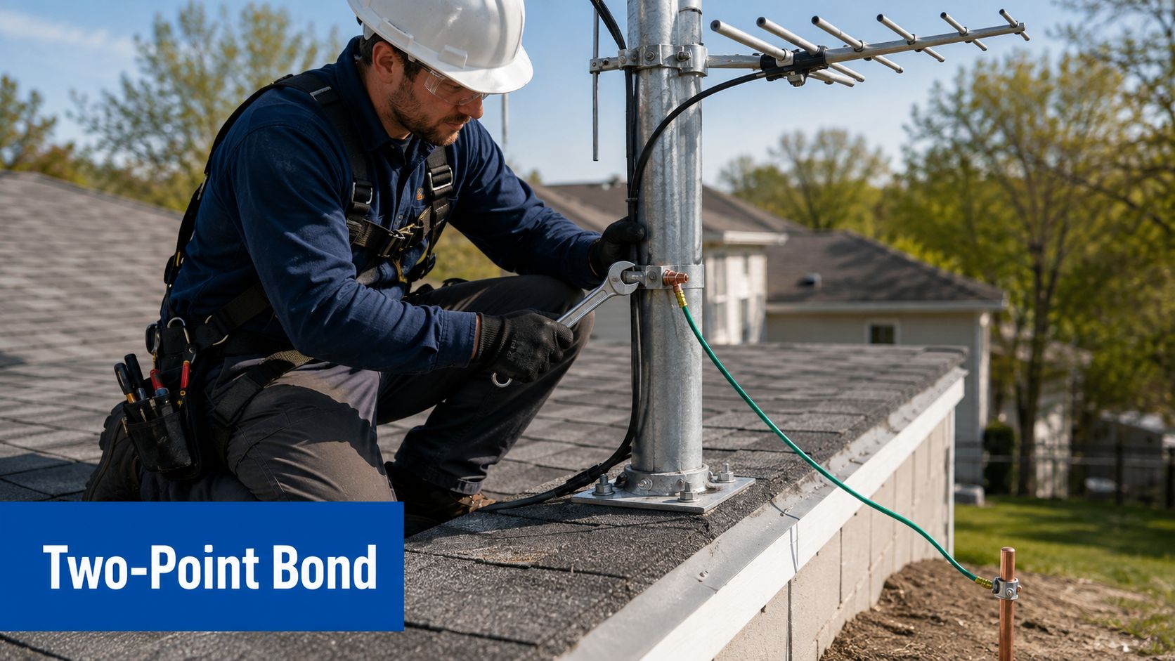
Practical rule: Don't coil excess bonding wire or route it around corners for appearance. Surge paths work better when they're direct.
Don't rely on a water pipe, window frame, or a separate unbonded ground rod without confirming the code path. If the terminology is unfamiliar, call DLG Electrical for earthing before making a connection. You can also review DigiDevice's 20-amp outlet wiring resource, but antenna bonding still needs to follow electrical and lightning-protection requirements.
Lightning guidance recommends an air-termination system for exposed antennas and surge protection at the cable entry. Where the antenna is exposed to lightning flashes, Class I surge protection is recommended, while Class II protection is recommended when an air-termination system protects it. Local code and the antenna manual control the final design.
Running the Coax Cable and Connectors the Right Way
Treat the feedline as one continuous outdoor-to-indoor route. Every connector, bend, clip, and roof entry creates another opportunity for water ingress, signal loss, or mechanical failure.
Start at the antenna
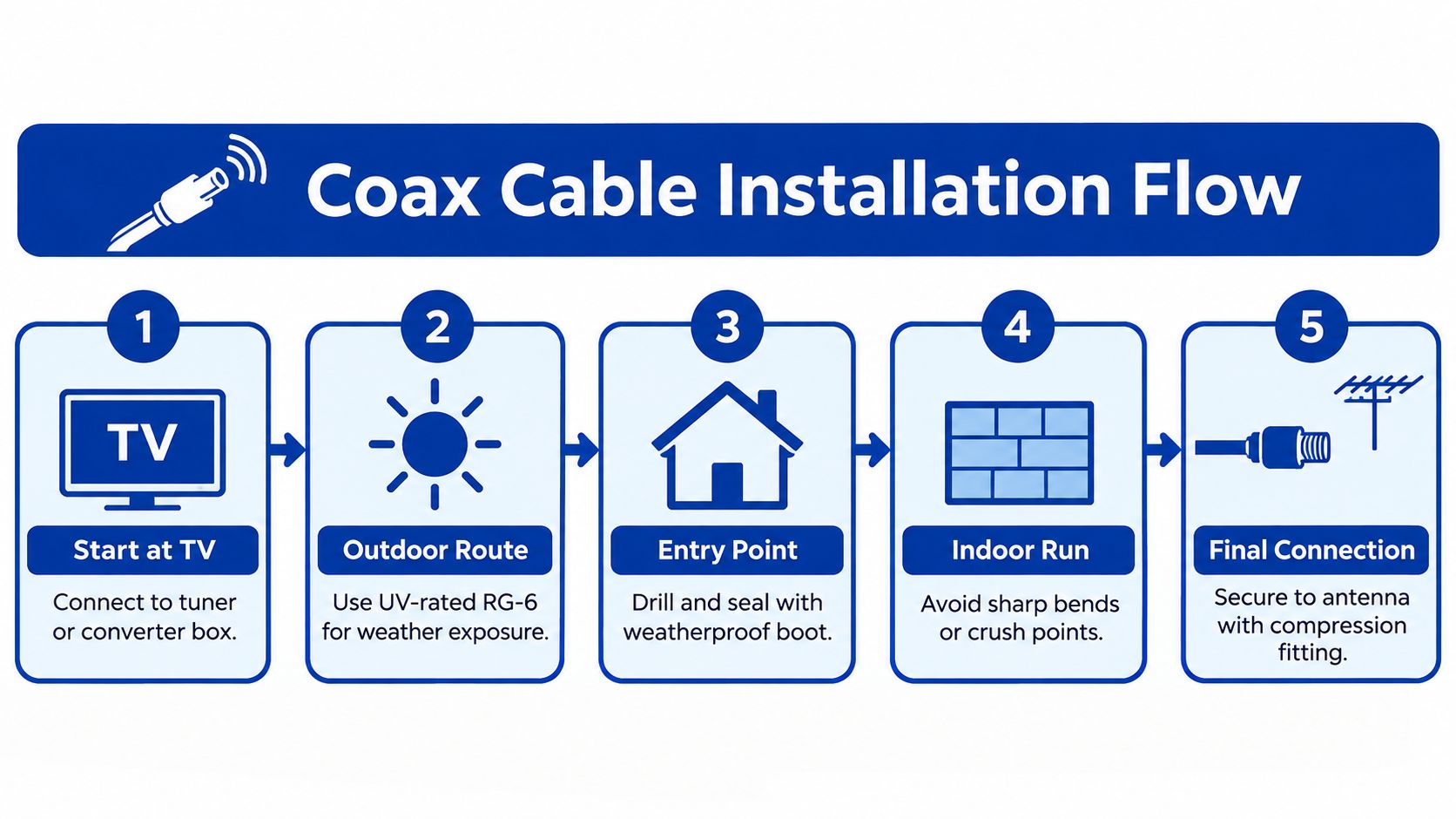
Use outdoor UV-rated RG-6, with a flooded or gel-filled jacket where the cable remains exposed to weather. Slide a weather boot over the F-connector before attaching it, hand-tighten the connector, then protect the joint with self-amalgamating rubber tape followed by a UV-stable vinyl layer.
Secure the coax with standoff clips so wind can't flex the connector. Keep the cable supported along the mast and avoid tight bends that deform the dielectric or braid.
At the roof entry, use a lead-in tube or weatherhead boot. Don't slide coax beneath shingles, where it can wick water into the roof assembly. Mount the grounding block close to the entry point, then make the bonding connection as direct as the building layout permits.
Finish the indoor run cleanly
Inside, staple the coax loosely enough that the jacket isn't crushed. Avoid long parallel runs beside Romex, and keep the cable away from sharp edges, heat sources, and moving hardware. Terminate with compression F-connectors rated for the exact cable type, rather than forcing a connector designed for another diameter.
Label both ends before connecting a splitter or tuner. If you later add a preamplifier, second television, or replacement cable, those labels prevent guesswork.
DigiDevice's coaxial cable routing guide can help you plan a cleaner electronics layout. For a rooftop run, the priorities remain weather sealing, strain relief, grounding near entry, and avoiding damage to the cable jacket.
Aiming, Scanning, and Verifying Your Signal
Antenna aiming is a measured adjustment, not a one-time guess. Start with the transmitter bearings from TV Fool, RabbitEars, or the FCC DTV map, using your full address so the terrain and local tower directions are relevant.
Point the narrow end or directional face toward the strongest transmitter cluster. A phone compass app is adequate for coarse aiming, but don't trust the compass alone. The television or tuner has the final evidence.
Use a second person as the meter operator
Have someone watch signal readings while you rotate the antenna in 10-degree increments. Pause 10 seconds at each position so the tuner can settle, then record the result for every must-have network.
Look for a stable picture, a signal level above roughly -65 dBm, and a clean signal-to-noise reading without pixelation. The -65 dBm benchmark comes from the practical installation guidance supplied for this process, so use it as a working reference rather than a universal guarantee.
The best aim is the position that keeps all required channels usable, not the position that produces one impressive reading.
Run a fresh channel scan after the antenna is secured. Success means the channels you watch lock in quickly, remain stable, and don't disappear when conditions change. If a marginal station improves while another must-have station gets worse, stop chasing the marginal one and choose the balanced orientation.
A cellular signal meter and a TV antenna meter solve separate problems. DigiDevice's explanation of whether cellular boosters work is relevant when a weak phone signal is being confused with weak over-the-air television reception.
Safety Checklist and Your Next Move
Before leaving the roof, inspect the installation as if someone else will service it later. A clean finish isn't cosmetic. It preserves the weather barrier, makes faults visible, and reduces the chance that the next adjustment becomes a risky rebuild.
Final roof inspection
- Check the mast: Confirm it's plumb on two sides, and verify that every U-bolt and structural fastener is seated firmly.
- Inspect the weather seals: Make sure exposed coax connectors are wrapped with self-amalgamating tape and protected from ultraviolet exposure.
- Verify the bonding path: Confirm the mast and coax grounding block connect to the building ground with approved clamps and an unbroken, direct conductor.
- Inspect surge protection: Verify the discharge or surge-protection unit is in line at the entry point and that the down-conductor path isn't interrupted.
- Secure loose cable: Remove loops that can catch wind, but don't create tight bends or crush points.
Inside the house, label both ends of every coax run at the splitter and television. Photograph the mast connection, grounding block, cable entry, and service-ground termination for your records. Save the tower coordinates and final antenna orientation so you can restore the setup after a severe storm.
Permission checks still matter after installation. If your local authority, landlord, HOA, or roof warranty requires approval, keep that documentation with the photos. Also inspect nearby gutters and roof drainage after the work. For homeowners who need a safe maintenance reference, this guide to gutter maintenance for Columbus homes reinforces the value of handling roof-edge work without unnecessary climbing.
A labeled, bonded, documented installation is easier to upgrade when you add a preamp, replace a damaged connector, or connect another tuner. If the reception test failed from the roof-edge position, don't force the project. An attic, balcony, or wall mount may be the safer and more effective answer.
DigiDevice offers practical electronics and connectivity products, including mobile signal equipment for home and office use, while this rooftop project depends on correct antenna mounting, coax routing, and grounding. Visit DigiDevice to review compatible gear, then choose the product only after you've confirmed the reception problem and the installation path.